cogvalveفارسی
Valve accessories
AI-generated product illustration. Final details are confirmed against the order specification.

Valve accessories

4 models in this family

Review the listed models and configurations in this family, then select one for a quotation request.

Selected model

Valve limit-switch assembly

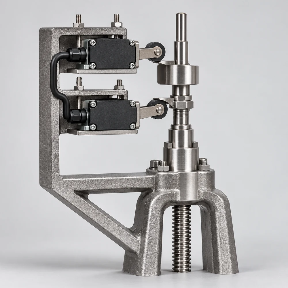
The limit-switch assembly indicates when the valve mechanism reaches the end of its travel. The shown arrangement places position contacts beside the stem and operating assembly so mechanical movement can provide a status indication. Select the contact arrangement, signal type, environmental protection and mounting for the control system and valve. Position indication alone does not measure leakage or provide continuous flow regulation.

Selected model specifications

FunctionEnd-of-travel indication
SignalPosition contact
MountingMatched to the valve mechanism

Models and configurations

Select a configuration. The family image changes only when the model has a distinct illustration.

Valve limit-switch assemblyFunction: End-of-travel indication · Signal: Position contact · Mounting: Matched to the valve mechanismThe limit-switch assembly indicates when the valve mechanism reaches the end of its travel. The shown arrangement places position contacts beside the stem and operating assembly so mechanical movement can provide a status indication. Select the contact arrangement, signal type, environmental protection and mounting for the control system and valve. Position indication alone does not measure leakage or provide continuous flow regulation.
Industrial valve bypass assemblyFunction: Auxiliary flow path · Arrangement: Bypass valve and connecting line · Compatibility: Matched to the main valve and lineA bypass provides a controllable auxiliary path around the main valve. In the shown arrangement, a smaller valve and connecting pipe join the two sides of the main body to permit flow through the auxiliary route. Select bypass size, materials, connections and the operating sequence for the process conditions. A bypass does not by itself replace the required isolation arrangement and operating procedure.
Reinforced packing and leak-detection lanternMain components: Reinforced packing / Lantern ring · Location: Valve stem sealing assembly · Lantern function: Leak-detection passageThis sealing arrangement combines reinforced packing with a lantern ring for leakage observation at the stem assembly. The section identifies the packing location and a lateral passage associated with the lantern ring. Specify the stuffing-box dimensions, sealing material and compatibility with the fluid, pressure and temperature of the selected valve. This is a sealing option rather than a complete electronic leak-detection system.
Valve security-lock arrangementFunction: Restricted valve operation · Arrangement: Mechanical lock / Padlockable option · Location: Stem or operating mechanismThe security-lock arrangement restricts access to the valve operating mechanism. The illustrated mechanical-lock and padlockable configurations act on the stem assembly to retain a selected position and restrict unauthorized operation. Specify the locking arrangement, required open or closed position and compatibility with the operator. Key details and the operating procedure depend on the selected construction.